
What is a DXF file? The basics, plainly explained
Updated: Aug 2, 20265 min read
DXF is the exchange format for cutting data. What is inside it, why machines can read it, and what separates a good DXF from an unusable one.
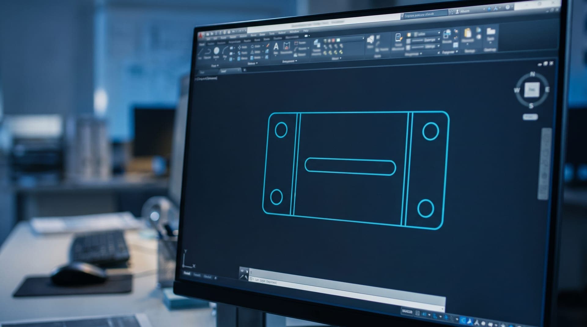
Anyone wanting a part cut for the first time hears almost the same sentence every time: »Just send us a DXF.« For someone who does not work in design, that is about as helpful as being asked for a wavelength instead of a colour. This article explains what lies behind the format, with no prior knowledge assumed.
A drawing, not a picture
The most important distinction first, because most misunderstandings hang off it: a DXF file is not an image. A photo or a scan consists of pixels — tiny coloured squares that form a shape when seen from a distance. Enlarge an image far enough and all you see is blocks. The machine finds no edge there, only a cloud of dots where nobody can say exactly where the contour runs.
A DXF describes geometry instead. The file does not say »it is black here«, it says »a straight line runs from point A to point B« and »a circle with radius 4 sits around point M«. That is a mathematical description, not a depiction. This is why it stays exact at any magnification, and why a cutting machine can derive a tool path from it without guesswork.
The abbreviation stands for Drawing Interchange Format. Autodesk, the maker of AutoCAD, published it in the early eighties so that CAD programs from different vendors could exchange drawings. That is still its role today: DXF is not the format you design in, it is the format you hand geometry over in. Rather like PDF for text — you do not write in PDF, you send in it.
What a DXF contains
A DXF is a plain text file. Open it in an editor and you see columns of numbers and keywords. A handful of terms is enough for practical purposes:
- Entities are the individual building blocks: lines, arcs, circles, polylines, splines. Every contour is assembled from them.
- Layers are levels the entities sit on. In manufacturing they are commonly used to separate the outer contour, internal cut-outs, engravings and pure construction lines.
- The header holds global settings, among them the drawing unit in use.
- Blocks are reusable groups, for example a hole pattern that appears in several places.
For cutting, almost only the contour geometry matters in the end. Dimensions, title blocks and borders are meant for humans; the machine ignores them — or, in the worst case, cuts them too, if they sit on the same layer as the contour.
Why there are so many DXF versions
The format has been developed for over forty years, and practically every AutoCAD generation brought a new revision with it: R12, 2000, 2007, 2013 and so on. Older programs often cannot read newer revisions. This is why manufacturing shops sometimes ask for a particular version explicitly.
R12 is a special case. This ancient revision knows neither splines nor many modern constructs — on saving, free-form curves are automatically broken down into many short straight segments. That sounds like a loss, but in manufacturing it is often an advantage: whatever survives R12 is guaranteed to be understood by any controller. If you do not know better, R12 or 2013 will almost always be right.
The units trap
A DXF stores coordinates as bare numbers. Whether a 100 means a hundred millimetres, a hundred centimetres or a hundred inches is recorded in the header — but not every program writes that entry, and not every program reads it. The result is the single most common source of trouble in data exchange: a part comes out of the machine a factor of 25.4 too large or too small because inches met millimetres somewhere along the way.
Whenever you send a DXF, state one check dimension in plain words, such as »long outer edge = 250 mm«. The shop can verify in ten seconds that the file arrived correctly. Without that dimension, the error only surfaces on the finished part.
What makes a good DXF
A file opening successfully does not yet mean you can manufacture from it. From a preparation standpoint, four points decide the matter:
- Closed contours. Every contour must be a complete loop. A gap of a hundredth of a millimetre is enough to turn an area into an open polyline — the controller then has no way of knowing what is inside and what is outside.
- No duplicate lines. Where two identical lines lie on top of each other, the machine may cut the same edge twice. That wastes time, burns out the cut edge and can distort the part.
- Only what is meant to be cut. Dimensions, borders, logos and construction lines belong either on their own layer or out of the file.
- A sensible origin and realistic coordinates. Parts sitting ten kilometres from the origin cause rounding errors on some controllers.
What a DXF cannot do
A classic DXF for cutting is flat. It describes a silhouette in a plane, not a body. Material thickness, bends, countersinks and threads are not in it. For a sheet metal part that is no problem as long as the additional details are supplied — for a three-dimensional component you need a 3D format such as STEP.
Nor does a DXF contain the material, the quantity, the surface finish or the tolerance. That information belongs in the order or in an accompanying technical drawing. Send a bare DXF with nothing else and at best you get a query, at worst a part in the wrong material.
Do I have to be able to do this myself?
No. Producing a DXF takes a CAD program and practice, and for a single part neither is usually worth it. The normal route is to supply whatever template you already have — a dimensioned hand sketch, an old piece of sheet as a sample, a drawing from a repair manual — and leave the tracing to someone who does it daily.
What decides the result is then not your CAD knowledge but the quality of your information: unambiguous dimensions, clear statements about radii and holes, and the point of the part. A hole meant to take an M8 bolt is laid out differently from one that merely passes a cable through.
Frequently asked questions
Can I simply open and view a DXF file?
Yes. Free viewers exist, and many CAD programs display DXF even in their free edition. A viewer is enough to look; changing it takes a CAD program.
Is DXF the same as DWG?
No. DWG is AutoCAD's internal format and holds more information, but it is less openly documented. DXF was created expressly for exchange between programs and is read by considerably more controllers.
Which DXF version should I supply?
If no version is specified, R12 or 2013 are the safest. R12 is read practically everywhere because it contains no modern constructs.
How many layers should the DXF file have?
A single layer carrying nothing but the contours to be cut is safest. Dimensions, drawing frames and construction lines belong elsewhere — on the same layer, the machine may well cut them too.
Do the contours have to be closed?
Yes. If the start and end point of a contour do not meet exactly, it is open — a gap of a few hundredths of a millimetre is invisible on screen, but the machine control derives no cutting path from it and either aborts or runs the contour open.
Does the DXF file have to be drawn at 1:1?
Yes. The machine reads the coordinates unchanged as manufacturing dimensions; it knows no scale factor. A drawing reduced to 1:2 yields a part half the size.
Why does my part come out of the machine at the wrong size?
Almost always because of units: the file was created in inches and read as millimetres, or the other way round. A check dimension stated in plain words prevents this reliably.
More articles
Got a template and need a DXF?
Upload a sketch, photo or PDF. You receive a fixed-price quote up front, no obligation, no account fees.
Start a request