
Why a photo alone is not enough: dimensions, scale and accuracy
Updated: Jul 30, 20264 min read
How a template becomes a dimensionally accurate part: reference edges, check dimensions, tolerances and the usual traps in measuring.
»The photo is razor sharp, you can see everything.« The sentence comes up often, and it is understandable. Still, however sharp an image, it describes only the shape of a part, not its size. This article explains what happens between template and dimensionally accurate part, and where it goes wrong in practice.
Shape is not size
An image contains ratios: this hole sits roughly a third of the way along, that edge is about twice as long as the other. What is missing is the absolute reference. Whether the part fits in a palm or covers a tabletop cannot be derived from the shape alone. Supplying that reference is precisely the job of the scale.
So a single dependable dimension turns a shape into a size. Everything else can be derived from it — provided the image is undistorted. And that is the second hurdle.
The perspective trap
Photograph a part at an angle and everything further from the camera is foreshortened. A square becomes a trapezium, a circle becomes an ellipse. To the eye this is barely disturbing, because the brain compensates for perspective automatically. For measurement it is fatal.
Lens distortion adds to it. Wide-angle shots — and a phone's main camera is a wide angle — bow straight lines slightly outwards towards the edges. In the centre of the frame the effect is small, at the edge it is pronounced. A part photographed filling the frame right into the corners is measurably distorted at the edge.
- Photograph square from above, camera parallel to the part.
- Keep some distance and zoom in rather than moving close. That noticeably reduces distortion.
- Place the part towards the centre of the frame rather than out into the corners.
- Put a ruler in the same plane as the part, not above or below it.
Reference edges instead of chains
How you dimension co-determines how accurate the result is. Two approaches are common, and one of them is considerably more robust.
With chain dimensioning you measure from element to element: first hole to second, second to third. That is convenient, but each individual measurement brings its own inaccuracy and they add up. By the fifth hole the error can already be plainly visible.
With datum dimensioning every element is measured from the same edge. Each dimension stands on its own, errors do not accumulate, and if one dimension is missing or wrong it affects only that element. For anything that has to fit together later, this is the right choice.
The practical benefit shows on a hole pattern: if all holes are dimensioned from the left and bottom outer edges, the part still fits when a single figure has to be corrected. In a chain, everything downstream shifts with it.
What tolerance means
No manufactured part hits a dimension exactly. It is always about a window the result may fall within. That window is the tolerance, and it is one of the few specifications that feeds straight through to the price: a tighter tolerance means more effort, slower machining and more scrap.
For cutting that means concretely: an outer contour that only has to be roughly right because it will not be visible anyway may be toleranced generously. A hole spacing used to bolt a part onto an existing mating part may not. The note »these two dimensions are critical, the rest may vary by a millimetre« is one of the most useful things you can supply.
The kerf
One point that regularly surprises beginners: cutting removes material. The beam or flame has a width — the kerf — and depending on process and thickness it runs between roughly a tenth of a millimetre and two millimetres.
If the machine ran exactly along the drawn line, the part would come out half a kerf too small and a hole half a kerf too large. The controller therefore offsets the tool path outwards or inwards automatically. This is standard and works reliably — provided the controller knows what is inside and what is outside. And it only knows that with closed contours.
Measuring an existing part
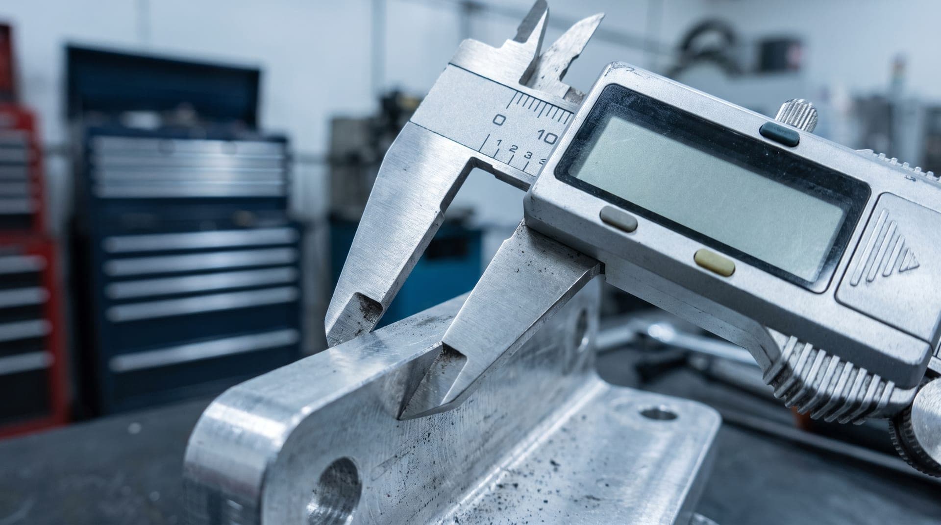
If you have a sample, measure it rather than estimating. A caliper costs little and beats any folding rule. A few pointers make the difference:
- Measure repeatedly and in several places. Sheet is rarely the same thickness everywhere, holes rarely perfectly round.
- Recognise worn, bent or corroded areas and name them explicitly. The broken original is the template for a sound part, not for the same damage.
- Measure holes internally rather than estimating centre to centre. The distance between two hole centres follows from the distance between the inner edges plus one diameter.
- On symmetrical parts, check whether they really are symmetrical. Often they are not quite, and then the question is whether that was intentional.
The check dimension
It is the cheapest insurance in the whole process: one single dimension, stated in plain words, against which the finished file can be verified. For example »long outer edge = 250 mm«. Open the DXF, measure that dimension, and within seconds you know whether a unit error crept in or a scale was applied wrongly.
Without a check dimension such an error only surfaces when the part comes out of the machine — and by then material and machine time have been spent. The effort of supplying it amounts to one sentence.
Frequently asked questions
How accurately can this be derived from a photo?
With a square shot, a good scale and a stated check dimension, deviations in the range of a few tenths of a millimetre are achievable. From an angled photo with no reference, no dependable statement is possible.
Do I have to specify tolerances?
Not necessarily, but it helps a great deal. Without a specification, normal workshop accuracy applies. If individual dimensions matter particularly, say so explicitly.
What is a kerf and do I have to allow for it?
It is the material the cutting beam removes. You do not have to allow for it — the machine controller compensates automatically, provided contours are closed. Draw the finished part at nominal size.
My part has to fit an existing mating part. What do you need?
Ideally the dimensions of the mating part, particularly the hole pattern and the mating edges. Where possible, photograph the mating part and state the critical dimensions separately.
More articles
Got a template and need a DXF?
Upload a sketch, photo or PDF. You receive a fixed-price quote up front, no obligation, no account fees.
Start a request