
The most common mistakes in drawing templates — and how to avoid them
Updated: Jul 30, 20265 min read
Open contours, duplicate lines, missing units: the typical pitfalls in templates for cutting, and what to do about them.
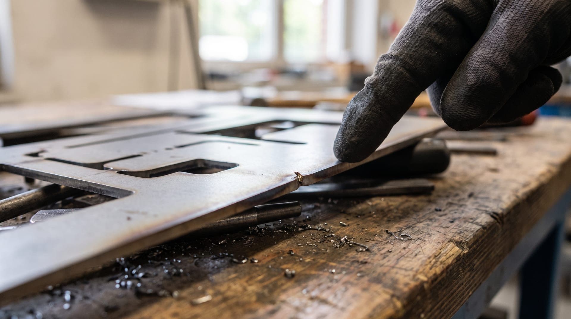
Anyone preparing templates for cutting daily sees very quickly that problems repeat themselves. They are rarely exotic special cases, but the same handful of pitfalls again and again. The good news: almost all of them can be avoided with little effort once you know about them.
1. Open contours
The classic and by far the most frequent case. A contour looks closed on screen but consists of individual lines whose endpoints do not meet exactly. The gap is often only a few thousandths of a millimetre and invisible at normal zoom.
For the machine the difference is fundamental. A closed contour encloses an area, there is an inside and an outside, and the controller can offset the kerf correctly. An open polyline is merely a line — the machine travels along it and the part comes out half a kerf too small, or it refuses the job altogether.
This is avoided by working consistently with snap functions in CAD and by joining individual segments into polylines. Anyone not using CAD software is unaffected by this problem — it only arises during drawing.
2. Duplicate lines
When copying, mirroring or tracing over repeatedly, two identical lines readily end up exactly on top of each other. This is not visible. The machine then cuts the same edge twice: the second pass meets an already open kerf, the beam goes into empty space, the edge burns out, and the part can come loose and tilt.
Proper preparation therefore always checks a drawing for duplicates before passing it on. Anyone drawing themselves should know their program's check function — every serious CAD package has one.
3. Missing or wrong units
A DXF stores coordinates as bare numbers. Whether a 100 means millimetres or inches follows from an entry in the file header that not every program writes or reads dependably. When a file created in inches meets a controller expecting millimetres, out comes a part off by a factor of 25.4.
One single sentence prevents this permanently: state a check dimension in plain words, such as »overall length = 250 mm«. It costs nothing and can be verified in seconds.
4. Dimensions and borders in the cutting file
A technical drawing contains dimension lines, figures, a title block and a border. All of it is meant for humans. If it sits in the DXF on the same layer as the contour, the machine may well cut it too — and out of the sheet comes a part with dimension figures burnt into it.
The solution is layer separation: cutting contours on their own layer, everything explanatory on others. Anyone supplying a drawing with dimensioning should state explicitly which elements are meant to be cut.
5. Splines instead of clean arcs
Splines are mathematically described free-form curves. They are handy when designing, but many older controllers cannot process them directly and break them into very many short straight segments. That leads to files with tens of thousands of segments, juddering movement and visibly faceted curves.
Where a curve is in truth a circular arc, it should be drawn as a circular arc. That is smaller, more precise and understood everywhere. The point becomes especially relevant with automatically traced scans: the curves produced there are almost always splines or polylines with needlessly many control points.
6. Holes too small and webs too thin
On screen, a two-millimetre hole in a ten-millimetre plate is no problem. In the machine it is: as a rule of thumb a hole should be at least as large as the material is thick. Below that the edge turns ragged, the hole becomes conical, or it cannot be produced at all.
The same applies to webs between two cut-outs. If a web gets too narrow it absorbs so much heat during cutting that it distorts or burns through. Where a delicate pattern is wanted, it should be discussed early — often the same result can be achieved with a different material thickness or a different process.
7. Contradictory dimensions
The individual dimensions do not add up to the overall dimension. Two views show different values for the same edge. A hole is given once as Ø 8 and once as Ø 8.5. Such contradictions arise easily when a drawing has been revised several times.
They almost always surface during tracing, because the geometry then fails to close. That is the cheapest moment to resolve them — considerably cheaper than after cutting. Anyone sending a revised drawing should briefly say which revision applies.
8. The important thing is not stated
The most frequent mistake is not a mistake in the drawing at all but an omission: the purpose is missing. A contour does not reveal whether a hole takes a bolt or passes a cable, whether an edge stays visible, whether the part has to fit an existing mating part.
That information costs two sentences and heads off most queries. It also makes it possible to point out that a given design will not work as intended — which is considerably more pleasant when it comes before cutting.
A short checklist
- Are all contours closed?
- Are duplicate lines sitting on top of each other?
- Is a check dimension stated in plain words?
- Are dimensioning and borders on their own layer?
- Are curves real circular arcs rather than splines?
- Are all holes at least as large as the material is thick?
- Do any dimensions contradict each other?
- Is it stated what the part is for?
Frequently asked questions
How do I tell whether my contour is closed?
In CAD programs a closed contour can be hatched as an area or have its area displayed. If that fails, there is a gap somewhere. Some programs have a dedicated check function for it.
Do I have to check my file myself?
No. Proper preparation covers exactly these checks. What is most useful is supplying the check dimension and the purpose — nobody can do that for you.
My converter turned a scan into a DXF. Is that enough?
Usually not. Such files consist of very many short segments and are not dimensionally accurate. Better to send the original template along — cleaner work can be done from it.
How small may a hole be?
As a rule of thumb at least as large as the material thickness. On thin sheet with laser cutting you can go below that; with plasma and thick material you cannot.
More articles
Got a template and need a DXF?
Upload a sketch, photo or PDF. You receive a fixed-price quote up front, no obligation, no account fees.
Start a request